UDMcb
1, 2 drives 12-60Vdc or 12-100Vdc, up to 13.3/40A
Economical 100V/40A, Dual & Single Axis PCB
Mounted EtherCAT® Drive Module
Powerful and Compact
- Two drives per module for Gantry control
- Voltage: 12-60Vdc or 12-100Vdc
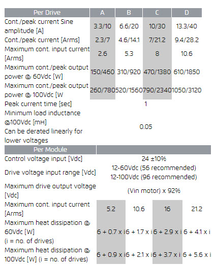
- Current: from 3.3/10 to 13.3A / 40A (cont./peak)
- PCB mounted to enable customised connectivity
Outstanding Speed and Resolution
- 2 Analog Sin-Cos 1Vptp encoders with frequency up to 500KHz
- Encoder multiplication of 4 to 4,096
- Automatic encoder offsets and gain compensation and error detection
- Dual feedback support
- Relays control outputs for motor dynamic braking
Smart Motion Related I/O
- 4 encoder registration MARK inputs
- 2 Position Event Generator (PEG) outputs
- 2 motor brake / relay outputs
- 2 analog inputs, 12 bit resolution, ±10V or 0-10V
- 2 analog outputs, 10 bit resolution, ±10V
- Safe Torque Off (STO)
The UDMCB is a line of economical and compact PCB mounted EtherCAT drive modules. |
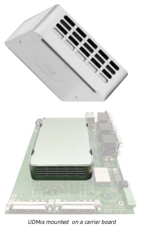 |
The UDMCB is specifically designed to complement the highest performance NPMPC Nano PWM drives and address the needs
for a more economical drives. It has the same form factor as the NPMPC and same connectivity.
One customized carrier board can be used for both modules.
Such a carrier board design enables customization of connectors, I/O configuration, STO and other safety related functions.
For prototype testing and carrier board design reference it is recommended to use the UDMPA.
The UDMCB is a slave that runs under any ACS EtherCAT® masters.
A comprehensive set of software support tools are provided for configuration, setup and tuning.
CE, UL (Pending)
EtherCAT® is registered trademark and patented technology, licensed by Beckhoff Automation GmbH, Germany
Drives
Type: digital current control with field oriented control and space vector
modulation.
Current ripple frequency: 40 kHz.
Current loop sampling rate: 20 kHz.
Current dynamic range: 1,500:1.
Programmable Current loop bandwidth: up to 5 kHz.
Commutation type: sinusoidal. Initialization with or without Hall sensors.
Switching method: advanced unipolar PWM.
Protection: Over and under voltage, Over current, Over-temperature, Phase to phase and phase to ground short (short circuit on one of the motor phases might damage the drive).
Supply
The module is fed by two power sources. A motor supply and a 24Vdc control supply. During emergency conditions there is no need to remove the 24Vdc control supply. (If STO is used, then there is also no need to remove th motor supply)..
Motor Drive Supply
Range: 12Vdc to 60Vdc or 12Vdc to 100Vdc,
Recommended range: 12-56Vdc for 60Vdc version, 12-96Vdc for 100Vdc version.
Current rating should be calculated based on actual load.
If regeneration resistor is required, it should be added in parallel to motor supply with activation at 62V for 60V version or 102V for the 100V version.
Control Supply
Range: 24Vdc ± 10%.
Maximum input current / power: 0.9A @21.6V/ 20W Without motor brakes.
Protection: reverse polarity. A 2A external fuse must be used.
Motor Type
Two- and three-phase permanent magnet synchronous (DC brushless/AC servo), DC brush, Voice coil, Two- and three-phase stepper (micro-stepping open or closed loop).
Feedback
Types: Incremental digital encoders (AqB), Hall inputs, analog Sin-Cos
(optional).
Incremental Digital Encoder: One per axis. A&B, I and Clk/Dir,
Type: Differential RS-422. Max. rate: 50M quad counts/sec.
Protection: Encoder error, not connected.
Sin-Cos Analog Encoder: One per axis
Type: 1Vptp, differential.
Programmable multiplication factor: x4 to 4096.
Maximum frequency: 500kHz.
Maximum acceleration with Sin-Cos encoder: 108 sine periods/second2.
Absolute Encoder (optional): EnDat 2.2 & 2.1(digital only), Biss-A/B/C.
Hall inputs: A set of three per axis.
Type: single-ended, 5V, source, open cathode. Input current: <7mA.
Feedback supplies: For all digital feedback devices: 5V, 0.5A (DGND).
For all analog feedback devices: 5V, 1.5A (AGND).
It is recommended to include a dedicated supply on the carrier board.
Digital I/O
For different I/O configurations see ordering options in the data Sheet.
Inputs
Safety: Left & right limit inputs per axis.
Type: 5/24V Sink/Source, single ended, opto-isolated. Input current 4-14mA.
Registration Mark: (High Speed Position Capture): Four, 5V/24V ±20%
opto-isolated, two terminals. Input current 4-14mA.
All dedicated inputs can be used as general purpose inputs.
Dedicated motor over temperature protection: for each axis.
Outputs
Motor Mechanical Brake: Two, 5/24V Sink/Source, single ended, opto-isolated, 0.1A.
PEG (Position Event Generator): Two, Pulse or State, Differential, RS422.
Pulse width: 26nSec to 1.75mSec. Maximum rate: 10MHz.
All dedicated outputs can be used as general purpose outputs.
Analog I/O
Analog Inputs: Two, 0-10V or ±10V, differential, 12 bit resolution.
Max. input frequency: 1 kHz. Offset: <100mV.
Analog Outputs: Two, ±10V, differential, 10 bit resolution.
Offset: ±100mV, Bandwidth: 5 kHz. Max. output load: 10KΩ, Noise/Ripple: <40mV.
STO (Safe Torque Off) - Optional
Supports STO implementation on the carrier board.
EtherCAT Communication
In and Out.
Environment
Operating range: 0 to + 40°C.
Storage and transportation range: -25 to +60°C.
Humidity (operating range): 5% to 90% non-condensing.
Dimensions
155 x 85 x 30 mm3.
Weight
320 gr.

|